
USB-C power input: a practical design checklist
Updated 5 September 2026
Replacing a barrel connector with USB-C is a power-input design task, not just a connector change. Define what the product needs, establish what the connected supply can provide, and decide what the product should do when those two do not match. This guide focuses on a product that receives power: a USB-C sink.
Separate the connector from the power agreement
A source supplies power; a sink receives it. The configuration-channel (CC) connection supports attachment detection and current advertisement. USB Power Delivery (PD) adds a protocol for negotiating power. A matching plug does not, by itself, establish the voltage and current available to your circuit.
ST’s AN5225 distinguishes default USB power, Type-C current advertisement at 5 V, and USB PD. Its Type-C examples include advertised 1.5 A and 3 A levels; they are capabilities to detect, not permission to assume every port provides 3 A. Source: ST AN5225 Rev 7, sections 3.1, 4.2 and 6.
USB-IF describes PD as enabling flexible power delivery. That describes the technology, not a guarantee about an individual charger, cable or product. Specify the combination your product supports instead of writing only “USB-C powered” in the requirements. Source: USB-IF’s Power Delivery overview.
Start with a power budget
Our suggested starting point is a list of operating modes: startup, normal operation, peak activity and any reduced-power mode. For each, record the required supply rails, expected load and acceptable behaviour. Keep assumptions separate from measurements.
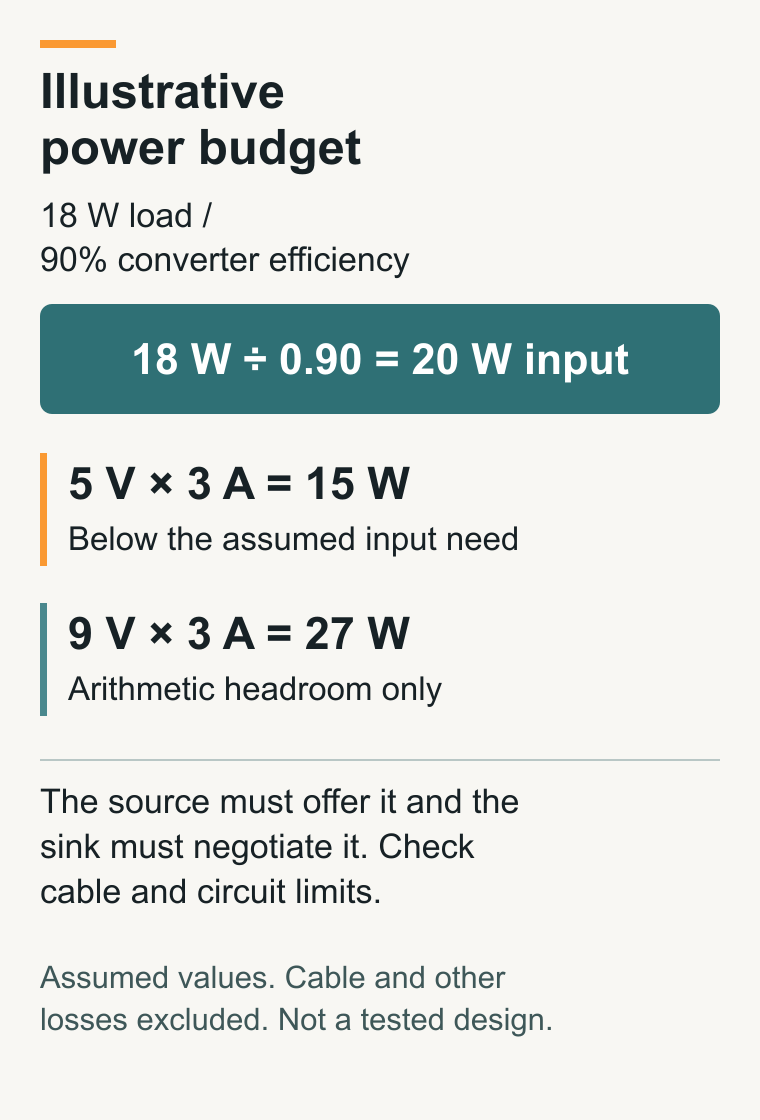
For an illustrative power budget, assume a load needs 18 W and its converter is 90% efficient at that operating point. The converter input needs 18 W ÷ 0.90 = 20 W. This simplified estimate excludes cable and other losses; a real budget must account for those too.
- 5 V at 3 A gives 15 W: insufficient for the assumed 20 W input requirement, even before those additional losses.
- 9 V at 3 A gives 27 W: arithmetic headroom, but only useful if the source offers that capability, the sink negotiates it, and the cable and circuit support it.
The useful decision is not “buy a larger charger”. It is whether the supported source profiles, conversion stage and product operating modes fit together. Do not mistake this example for a recommended voltage, component choice or validated margin.
Choose the controller and power path together
A controller’s configuration is part of the design. For example, TI’s TPS25730 uses resistor pin settings to configure sink voltage and current requirements. Its documentation also describes integrated or externally controlled power-path arrangements. Those are device-specific features, not a promise that every USB-C controller behaves the same way. Source: TPS25730 datasheet, sections 8.3.3, 8.3.10–8.3.14 and 9.1.
For your design review, trace the path from receptacle to load. Check the selected components’ operating limits, protection functions, startup behaviour, thermal requirements and layout guidance against the actual design. Identify which functions are inside the chosen controller and which need external circuitry. Do not treat a protection feature on one integrated circuit as proof that the complete input is protected.
Plan for an unsuitable supply
The TPS25730 provides a useful example of why configuration matters: its documentation describes a capability-mismatch indication when offered power does not meet configured requirements. That indication is not extra power. Read the exact device’s power-path and status behaviour rather than assuming a mismatch automatically produces your preferred system response. Source: TPS25730 datasheet, sections 8.3.11–8.3.14.
Choose the product response deliberately. Depending on its requirements, it might remain off, display an insufficient-power message, or enter a defined lower-power mode. These are proposed design options, not interchangeable safety measures. Specify which loads may start, when they may start, and how the product should recover after a suitable supply is connected.
Turn compatibility into a test plan
Use the following as a suggested review matrix. A responsible engineer should select the equipment, limits and bench procedures for the actual circuit. Do not deliberately short connector pins or exceed ratings to improvise a fault test.
- Supported supply: record the source capability, selected power agreement and observed startup sequence.
- Insufficient supply: verify the specified reduced-power or refusal behaviour, not simply whether an indicator lights.
- Plug orientation: repeat the intended connection checks with the reversible plug in both orientations.
- Operating transitions: check the agreed startup, peak-load and return-to-idle cases within the approved test limits.
- Detach and reconnect: verify shutdown and recovery against written requirements, including any retained state.
Keep the board revision, controller configuration, source and cable identifiers, expected result and observed result with each record. Separate calculations, configuration checks and executed measurements. An untested combination should remain marked untested.
Before releasing the next board revision
- Required operating power and supported input profiles are explicit.
- The controller configuration matches the product requirements.
- Cable, power-path and conversion-stage limits have been reviewed.
- Insufficient-power and recovery behaviour are defined.
- Test records identify the combinations actually exercised and remaining gaps.
For help turning these requirements into a reviewable design and test plan, explore DVAR’s electronic hardware and automated test equipment services. Bring your current power budget, input requirements and development stage.
Further reading
Start with the USB-IF overview, then use the linked ST and TI documents for the specific implementation concepts discussed here. This is a bounded design-planning guide, not a complete USB specification, compliance assessment or circuit construction recipe.
Sources checked 5 September 2026. ST AN5225 Rev 7 (June 2023) and TI TPS25730 SLVSGP9 (October 2023) are cited for the specific concepts above, not as statements of the latest USB revision.